Saturday, August 5, 2017

Basic Blink

A very simple circuit using very simple code. Pin (13) is an output for the LED. This output pin only has two output states:
  • ON or HIGH (+5V)
  • OFF or LOW (0V).

The program:
  • Turns the LED on - delays 1 second (1000 milliseconds)
  • Turns the LED off - delays 1 second (1000 milliseconds)
  • repeats this behavior over and over again.

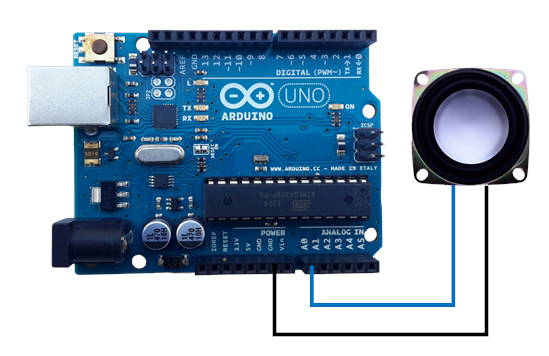
Hookup for Basic Blink


--------------------------- Copy Code Below

void setup()
{
pinMode(13, OUTPUT);
}
void loop()
{
digitalWrite(13, HIGH);
delay(1000); //1 second (1000 ms per second)
digitalWrite(13, LOW);
delay(1000);
}

--------------------------- Copy Code Above

Going Further:

1) Replace literal value (13 here) 
with a variable for delay
2) Set the blink rate using a potentiometer
3) Use variable frequency Blink with a high power LED to create a Stroboscope

Alternate Blink

Alternately Blink two LEDs. Requires the addition of a single LED to Blink. Drive one LED HIGH while the other LED is driven LOW, delay, and reverse the situation --- Simple.


------------ Copy Code below ---------------

void setup() {
  pinMode(13, OUTPUT);
  pinMode(12, OUTPUT);
}

void loop() {
  digitalWrite(13, HIGH);
  digitalWrite(12, LOW);
  delay(1000);
  digitalWrite(13, LOW);
  digitalWrite(12, HIGH);
  delay(1000);
}

------------ Copy Code above ---------------

Going Further:


Multicolor LED Blink

This program blinks a multi-color LED through the colors Red, Blue and Green. The multi-color LED actually three LEDs - A Red, Green and Blue LED. Other colors are possible since combinations of colors and mixing of colors are seen as new colors.


NOTE: The Green lead of the LED (G) is located on the right side of the connection diagram above (connections matter!).


NOTE: Some Multi-color LEDs connections can vary from the connection diagram above and you may need to connect the leads differently than shown above. 

Challenge: make the LED blink through the colors Red, Orange, Yellow, Green, Cyan, and Blue 

--------------------------- Copy Code Below

void setup()
{
  pinMode(8, OUTPUT); //Red
  pinMode(9, OUTPUT); //Green
  pinMode(10, OUTPUT); //Blue  
}

void loop()
{
  digitalWrite(8, HIGH); //Red ON
  delay(1000);
  digitalWrite(8, LOW); //Red OFF
  digitalWrite(9, HIGH); //Green ON
  delay(1000);
  digitalWrite(9, LOW); //Green OFF
  digitalWrite(10, HIGH); //Blue ON
  delay(1000);
  digitalWrite(10, LOW); //Blue OFF
  delay(1000);
}

--------------------------- Copy Code Above

Blink a Digit


Blink a Digit

This is an example of conditional looping (iteration). In this activity a for statement is used to blink the LED the number of times specified by the global variable called digit. The for statement uses a variable x to loop a digit number of times. As long as the for statement is true it will continue to loop but once x becomes greater than digit the loop condition tests false and looping stops. Since the for statement is contained in the loop function the process repeats again and again each time after a 1 second delay.

Hookup for Blink a Digit


--------------------------- Copy Code Below

int digit = 7; //global, integer variable (seen in every function)
void setup()
{
pinMode(13, OUTPUT);
}
void loop()
{    
    for(int x = 1; x <= digit; x++)
    {
    digitalWrite(13, HIGH);
    delay(200);
    digitalWrite(13, LOW);
    delay(200);
    }
delay(1000);
}

------------------------ End of Code

Going Further:: 

1) Blink out the value of a sensor.

Blink a Digit in Binary


Blink a digit in Binary

Here we create an Arduino function which uses a conditional statement to blink out a number in binary. The digit is evaluated and displayed from the least significant digit to the most significant digit. Only four bit are displayed since 4 bits are enough to display any digit.

Hookup for Blink a digit in Binary


--------------------------- Copy Code Below

void setup()
{
pinMode(13, OUTPUT);
}
void loop()
{
blinkBin(11);  // Call the function to convert a number to binary
}

void blinkBin(int digit) //function creation. The function is created outside setup and loop
{
  for(int n = 0; n < 4; n++)
{
    if (bitRead(digit,n) == 1) //Long blink for 1 //Use the bitRead function to read each bit of a number
       {
        digitalWrite(13, HIGH);
        delay(500);
       digitalWrite(13, LOW);
       delay(500);
       }
       else //Short blink for 0
       {
         digitalWrite(13, HIGH);
         delay(200);
         digitalWrite(13, LOW);
         delay(500);
       }
  }

delay(3000);
}

Blink a Temperature (LM 36)

Blink a Temperature

For this setup we are only adding an LM-36 temperature sensor to the previous setup (blink a number). First we take a reading from the sensor and break it up into the Lease Significant Digit LSD and the Most Significant Digit MSB. Each digit is blinked out one a time starting from the MSB and followed by the LSB.


Hookup for Blink a Temperature


--------------------------- Copy Code Below

// Blinks out the temperature in Centigrade
// Only handles two digit temperatures will not print out negative temperatures

float blinkNum;
byte dl;
byte dm;

void setup()
{
  pinMode(13, OUTPUT);
}

void loop()
{


 float voltage = analogRead(A0) * 5.0;
 voltage /= 1024.0;

 float temperatureC = (voltage - 0.5) * 100 ;  //converting from 10 mv per degree wit 500 mV offset

blinkNum = (int) temperatureC;

//blinkNum = ((analogRead(A0) * 4.88)-500)/10;


dm = (byte) blinkNum /10; // cast float as byte
dl = (byte) blinkNum % 10; // cast float as byte

  blinkX(dm);
  delay(300);
  blinkX(dl);
}

void blinkX(int blinkTimes)
{
  if (blinkTimes > 0)
  {
  for(int x = 0; x < blinkTimes; x++)
  {
    digitalWrite(13, HIGH);
    delay(200);
    digitalWrite(13, LOW);
    delay(200);
  }
  }
  else // if  > 0
  {
    digitalWrite(13,HIGH); //Zero is a quick blink
    delay(50);
    digitalWrite(13,LOW);
    delay(50);
  }
delay(3000);
}

--------------------------- Copy Code Above

TinkerCad Link:
https://www.tinkercad.com/things/49j1ynzkLJ2-blink-out-temperature-from-tmp-36/editel

}

Knight Rider (Brute Force)

Knight Rider


The Knight Rider effect is interesting way to make LEDs create a back and forth LED pattern. The code can be shortened and is more flexible using an array to control the effect.

Hookup for Knight Rider Brute Force

--------------------------- Copy Code Below
void setup() 
{
  pinMode(8, OUTPUT);
  pinMode(9, OUTPUT);
  pinMode(10, OUTPUT);
  pinMode(11, OUTPUT);
  pinMode(12, OUTPUT);
  pinMode(13, OUTPUT);
}

void loop()
{
  digitalWrite(13, HIGH);
  delay(1000);
  digitalWrite(13, LOW);
  digitalWrite(12, HIGH);
  delay(1000);
  digitalWrite(12, LOW);
  digitalWrite(11, HIGH);
  delay(1000);
  digitalWrite(11, LOW);
  digitalWrite(10, HIGH);
  delay(1000);
  digitalWrite(10, LOW);
  digitalWrite(9, HIGH);
  delay(1000);
  digitalWrite(9, LOW);
  digitalWrite(8, HIGH);
  delay(1000);
  digitalWrite(9, HIGH);
  digitalWrite(8, LOW);
  delay(1000);
  digitalWrite(9, LOW);
  digitalWrite(10, HIGH);
  delay(1000);
  digitalWrite(10, LOW);
  digitalWrite(11, HIGH);
  delay(1000);
  digitalWrite(11, LOW);
  digitalWrite(12, HIGH);
  delay(1000);
  digitalWrite(12, LOW);
}
--------------------------- Copy Code above

Going Further:

1) Control the delay using a variable instead of a literal
2) Use an array to address output pins instead literal pin numbers 

Knight Rider (Using Array)

Knight Rider (Array)

Using the "Brute Force" for the Knight Rider program we found ourselves repeating the same commands over and over again while only changing the pin number with each program step. With the code below we will create and use an array named Led[] to cycle through each LED. Incrementing the index variable for the array changes each LED pin number programatically instead of creating a large amount of unnecessary code. By using a array to cycle through pins the code we use is drastically reduced.


Hookup for Knight Rider Using Array

NOTE: Leds should be installed with short leads negative.

//--------------------------- Copy Code Below ------------

int dT = 50; //Global Variable
int Led[] = {13,12,11,10,9,8}; //An array of pin numbers. First element of the array (element 0) is on the left of the array

void setup()
{
  pinMode(13, OUTPUT); //All pins involved need to be designated as outputs
  pinMode(12, OUTPUT);
  pinMode(11, OUTPUT);
  pinMode(10, OUTPUT);
  pinMode(9, OUTPUT);
  pinMode(8, OUTPUT);
}

void loop()
{

for (int x = 0; x <= 5; x++) //Blink to the right from pin 13 to pin 8 (counting up)
{
  digitalWrite(Led[x], HIGH); // Turn ON current LED
  digitalWrite(Led[x-1], LOW); //Turn OFF prior LED
  delay(dT);
}

for (int x = 5; x >=0; x--) //Blink to the left from pin 8 to pin 13 (counting down)
{
  digitalWrite(Led[x], HIGH); //Turn ON current LED
  digitalWrite(Led[x+1], LOW); //Turn OFF prior LED
  delay(dT);
}

}

//--------------------------- End of code -------------

Moving Dot Display of Voltage

Moving Dot Display of Voltage

Without changing our LED layout we can now display a voltage value by lighting up LEDs in succession as the input voltage increases.


--------------------------- Copy Code Below
byte sensorPin = A0;
int sensorValue;

byte led1 = 8;
byte led2 = 9;
byte led3 = 10;
byte led4 = 11;
byte led5 = 12;
byte led6 = 13;

void setup()
{
pinMode(led1,OUTPUT);
pinMode(led2,OUTPUT);
pinMode(led3,OUTPUT);
pinMode(led4,OUTPUT);
pinMode(led5,OUTPUT);
pinMode(led6,OUTPUT);
}

void loop()
{
sensorValue = analogRead(sensorPin);

if (sensorValue >=150 && sensorValue <160)
{
digitalWrite(led1, HIGH);
}
else if (sensorValue >= 160 && sensorValue <170)
{
digitalWrite(led2, HIGH);
}
else if (sensorValue >=170& sensorValue <180)
{
digitalWrite(led3, HIGH);
}
else if (sensorValue >=180 && sensorValue <190)
{
digitalWrite(led4, HIGH);
}
else if (sensorValue >=190 && sensorValue <200)
{
digitalWrite(led5, HIGH);
}
else if (sensorValue >=200)
{
digitalWrite(led6, HIGH);
}
delay(100);

digitalWrite(led1,LOW);
digitalWrite(led2,LOW);
digitalWrite(led3,LOW);
digitalWrite(led4,LOW);
digitalWrite(led5,LOW);
digitalWrite(led6,LOW);
}

--------------------------- End of Code

Things to do:

- Calculate sensor values which will allow the Arduino to discern voltages in one volt increments (and 1/2 volt increments).
NOTE: The resolution of the AD converter is 0.00488 volts per unit (5 Volts/1024 increments) 
- Create an over-voltage alarm to detect when the voltage is over 4 volts
-  Create a device to measure the charge on a 12 volt battery in 1 volt increments. Should be able to measure up to 13 volts and alarm when the voltage is less than 10 volts.

NOTE: You must use a voltage divider that will not allow the Arduino analog input voltage to exceed 5 volts. 

Moving Dot Display of Temperature (LM-36)


Moving Dot Display of Temperature

Without changing our LED layout we can now display a temperature value by lighting up LEDs in succession as the temperature increases.

Connection for Moving Dot Display of Temperature


--------------------------- Copy Code Below

byte sensorPin = A0;
int sensorValue;

byte led1 = 8;
byte led2 = 9;
byte led3 = 10;
byte led4 = 11;
byte led5 = 12;
byte led6 = 13;

void setup()
{
pinMode(led1,OUTPUT);
pinMode(led2,OUTPUT);
pinMode(led3,OUTPUT);
pinMode(led4,OUTPUT);
pinMode(led5,OUTPUT);
pinMode(led6,OUTPUT);
}

void loop()
{
sensorValue = analogRead(sensorPin);

if (sensorValue >=150 && sensorValue <160)
{
digitalWrite(led1,HIGH);
}
else if (sensorValue >= 160 && sensorValue <170)
{
digitalWrite(led2,HIGH);
}
else if (sensorValue >=170& sensorValue <180)
{
digitalWrite(led3,HIGH);
}
else if (sensorValue >=180 && sensorValue <190)
{
digitalWrite(led4,HIGH);
}
else if (sensorValue >=190 && sensorValue <200)
{
digitalWrite(led5,HIGH);
}
else if (sensorValue >=200)
{
digitalWrite(led6,HIGH);
}
delay(100);

digitalWrite(led1,LOW);
digitalWrite(led2,LOW);
digitalWrite(led3,LOW);
digitalWrite(led4,LOW);
digitalWrite(led5,LOW);
digitalWrite(led6,LOW);
}

Moving dot display of Distance

Moving Dot Display of distance (Ultrasonic)

The further the object is from the sensor the more LEDs turn on. Each LED is calibrated for 10cm. If you're using a 4 pin ultrasonic sensor (eg HC-SR04) simply jumper the echo (sig) and the trig pin together.


Challenge add a sound output alarm when things get too close

--------------------------- Copy Code Below
const int pingPin = 7;

void setup()
{
// initialize serial communication:
Serial.begin(9600);
}

void loop()
{
// establish variables for duration of the ping,
// and the distance result in inches and centimeters:
long duration;
long cm;

// The PING))) is triggered by a HIGH pulse of 2 or more microseconds.
// Give a short LOW pulse beforehand to ensure a clean HIGH pulse:
pinMode(pingPin, OUTPUT);
digitalWrite(pingPin, LOW);
delayMicroseconds(2);
digitalWrite(pingPin, HIGH);
delayMicroseconds(5);
digitalWrite(pingPin, LOW);

// The same pin is used to read the signal from the PING))): a HIGH
// pulse whose duration is the time (in microseconds) from the sending
// of the ping to the reception of its echo off of an object.
pinMode(pingPin, INPUT);
duration = pulseIn(pingPin, HIGH);

// convert the time into a distance
 cm = microsecondsToCentimeters(duration);

if (cm > 2 && cm < 4)
digitalWrite(13, HIGH);
else if (cm > 4 && cm < 6)
digitalWrite(12, HIGH);
else if (cm > 6 && cm < 8)
digitalWrite(11, HIGH);
else if (cm > 8 && cm < 10)
digitalWrite(10, HIGH);
else if (cm > 10 && cm < 11)
digitalWrite(9, HIGH);
else if (cm > 12)
digitalWrite(8, HIGH);
  
 Serial.print(cm);
 Serial.print("cm");
 Serial.println();
 delay(100);
if (cm < 10)
{
tone(6, 1000);
}
else
{
noTone(6);
}
 digitalWrite(8, LOW);
digitalWrite(9, LOW);
digitalWrite(10, LOW);
digitalWrite(11, LOW);
digitalWrite(12, LOW);
digitalWrite(13,LOW);
}

long microsecondsToCentimeters(long microseconds)
{
  // The speed of sound is 340 m/s or 29 microseconds per centimeter.
  // The ping travels out and back, so to find the distance of the
  // object we take half of the distance traveled.
  return microseconds / 29 / 2;
}

Light-Activated Sound

Light-Activated Sound

Now lets have fun with sound. Shining a light on the photocell will produce a sound ☺


Hookup for Light-Activated Sound


--------------------------- Copy Code Below
int sensorValue;

void setup()
{
pinMode(13, OUTPUT);
}
void loop()
{
sensorValue = analogRead(A0);
if (sensorValue > 500)

  //digitalWrite(13, LOW);
  tone(13,1000);
}
else
{
  //digitalWrite(13, HIGH);
  noTone(13); }
}

Clapper

Clap On/ Clap Off


Pin Connections:

Sensor Out -- Pin 8
Sensor Vcc -- 5V
Sensor GND - GND

-------------------------- Copy code below
int led = 13;
int soundPin = 8;
bool ledstate = LOW;
bool clap = LOW;
void setup()
{
pinMode(13,OUTPUT);
pinMode(12, INPUT);
//Serial.begin(9600);
}
void loop()
{
clap = digitalRead(soundPin);
//Serial.println(value);
if(clap == HIGH && ledstate == LOW)
{
 ledstate = HIGH;
 digitalWrite(led,HIGH);
 delay(300);
}
else if(clap == HIGH && ledstate == HIGH)
{
ledstate = LOW;
digitalWrite(led,LOW);
delay(300);
}

//delay(100);
}

Simple Light Theremin

Simple Light Theremin

This project creates sounds of different frequencies based on the amount of light reaching the photocell.
For best performance use a real, electromagnet speaker instead of a piezo speaker.
Hookup for simple Light Theremin


--------------------------- Copy Code Below

int sensorValue;

void setup()
{
  pinMode(13, OUTPUT);
}

void loop()
{
sensorValue = analogRead(A0);
tone(13,sensorValue); //scale sensorValue for higher pitch

}


Tap for Tune

Tap for Tune

Play a tune every time the speaker is tapped. Uses analog input A0 to both detect and play the tune.


--------------------------- Copy Code Below
#define NOTE_A2  110
#define NOTE_AS2 117
#define NOTE_B2  123
#define NOTE_C3  131
#define NOTE_CS3 139
#define NOTE_D3  147
#define NOTE_DS3 156
#define NOTE_E3  165
#define NOTE_F3  175
#define NOTE_FS3 185
#define NOTE_G3  196
#define NOTE_GS3 208
#define NOTE_A3  220
#define NOTE_AS3 233
#define NOTE_B3  247
#define NOTE_C4  262
#define NOTE_CS4 277
#define NOTE_D4  294
#define NOTE_DS4 311
#define NOTE_E4  330

// notes in the melody: shave and and a haircut
int melody[] = {NOTE_C4, NOTE_G3, NOTE_G3, NOTE_A3, NOTE_G3, 0, NOTE_B3, NOTE_C4};
// note durations: 4 = quarter note, 8 = eighth note, etc
int noteDurations[] = {4, 8, 8, 4, 4, 4, 4, 4};
byte tapCount = 0;
long int tapTime = millis();
void setup()
{
}
void loop()
{
int sensorValue = analogRead(A0);
Serial.println(sensorValue);

 //detect a tap
    if(sensorValue > 10)
    {
    delay(100);
    pinMode(A0, OUTPUT);
    playTune();
    pinMode(A0, INPUT);
    delay(100);
    }
}
void playTune()
{
for (int Note = 0; Note < 8; Note++)
{
int noteDuration = 1000 / noteDurations[Note];
tone(A0, melody[Note], noteDuration);
int pauseBetweenNotes = noteDuration * 1.30;
delay(pauseBetweenNotes);
noTone(A0);}
}

--------------------------- Copy Code Below
Things to do:

1) Use the tap detection portion of the program to turn devices on and off
2) Create a combination lock using tap detection
3) Build a reaction detector that measure time between taps
4) Use the detector as a target game for airsoft gun or ping pong balls
5) Use speaker, with small weight attached to cone, to detect acceleration by measuring max signal from speaker
6) Use as a user interface for menu of options by tapping menu item number

Tap and Talk

Tap and Playback

Counts the number of times the speaker is tapped and reports back the number of taps with a series of tones. Works best with larger speakers. Have Fun!


--------------------------- Copy Code Below
/*

Reports a tone the number of times a speaker is tapped
Speaker is connected between A0 and ground
Don't push the speaker too hard!!
Add a potentiometer for setting the threshold pulse from speaker
A piezo disk can be used with a 10k resistor in parallel with the disk
the threshold signal must be adjusted for a disk and you can tape
it to a table or box to help it sound louder
Created by Dorian McIntire - dorianmc@gmail.com

*/

byte tapCount = 0;
long int tapTime = millis();

void setup()
{
}
void loop()
{
int sensorValue = analogRead(A0);

if(sensorValue > 5) //detect a tap
  {
    delay(50);
    tapCount = tapCount + 1; //increment tap count
    tapTime = millis(); //record current system time
  } //end if 1
pinMode(A0,OUTPUT);

if (tapTime < (millis() - 400)) //if more than 0.4 seconds have elapsed since last tap
{
  for(int x=0; x < tapCount; x++)
    {
      tone(A0,1500);
      delay(200);
      noTone(A0);
      delay(200);
    }//end for
  pinMode(A0,INPUT);
  tapCount = 0;
}//end if 2

delay(5); // delay in between reads for stability
} // end loop

--------------------------- Copy Code Above

Going Further

1.    Use to make a combination lock choose the number of taps for a basic lock or reprogram to enter as many digits as possible for your combination
2.    Use as an input device to select a menu option
3.    Build a calculator using the speaker to input a number

Tap increasing pitch


Tap Increasing Pitch

Counts the number of times the speaker is tapped and reports back the number of taps with a series of tones. Works best with larger speakers. Have Fun!


--------------------------- Copy Code Below
/*

Reports a tone the number of times a speaker is tapped
Speaker is connected between A0 and ground
Don't push the speaker too hard!!
Add a potentiometer for setting the threshold pulse from speaker
A piezo disk can be used with a 10k resistor in parallel with the disk
the threshold signal must be adjusted for a disk and you can tape
it to a table or box to help it sound louder
Created by Dorian McIntire - dorianmc@gmail.com

*/

byte tapCount = 0;
long int tapTime = millis();

void setup()
{
}
void loop()
{
int sensorValue = analogRead(A0);

if(sensorValue > 5) //detect a tap
  {
    delay(50);
    tapCount = tapCount + 1; //increment tap count
    tapTime = millis(); //record current system time
  } //end if 1
pinMode(A0,OUTPUT);

if (tapTime < (millis() - 400)) //if more than 0.4 seconds have elapsed since last tap
{
  for(int x=0; x < tapCount; x++)
    {
      tone(A0,1500);
      delay(200);
      noTone(A0);
      delay(200);
    }//end for
  pinMode(A0,INPUT);
  tapCount = 0;
}//end if 2

delay(5); // delay in between reads for stability
} // end loop

--------------------------- Copy Code Above

Going Further

1.    Use to make a combination lock choose the number of taps for a basic lock or reprogram to enter as many digits as possible for your combination
2.    Use as an input device to select a menu option
3.    Build a calculator using the speaker to input a number

Wednesday, August 2, 2017

Double Servo

Double Servo

Automatically controls two servos. Each servo could control an separate axis of a simple robot.


 -------- Code below -----------

#include <Servo.h>

Servo myservo1;  // create a servo object to control a servo1
Servo myservo2;  // create a servo object to control a servo2
// twelve servo objects can be created on most boards

int pos = 0;    // variable to store the servo position

void setup() {
  myservo1.attach(9);  // attaches the servo on pin 9 to the servo object
  myservo2.attach(10);  // attaches the servo on pin 9 to the servo object
}

void loop() { //control for servo1
  for (pos = 0; pos <= 180; pos += 1) { // goes from 0 degrees to 180 degrees
    // in steps of 1 degree
    myservo1.write(pos);              // tell servo to go to position in variable 'pos'
    delay(15);                       // waits 15ms for the servo to reach the position
  }
  for (pos = 180; pos >= 0; pos -= 1) { // goes from 180 degrees to 0 degrees
    myservo1.write(pos);              // tell servo to go to position in variable 'pos'
    delay(15);                       // waits 15ms for the servo to reach the position
  }

// control for servo2
  for (pos = 0; pos <= 180; pos += 1) { // goes from 0 degrees to 180 degrees
    // in steps of 1 degree
    myservo2.write(pos);              // tell servo to go to position in variable 'pos'
    delay(15);                       // waits 15ms for the servo to reach the position
  }
  for (pos = 180; pos >= 0; pos -= 1) { // goes from 180 degrees to 0 degrees
    myservo2.write(pos);              // tell servo to go to position in variable 'pos'
    delay(15);                       // waits 15ms for the servo to reach the position
  }

}